What Is FEA and When Does Your Product Actually Need It?
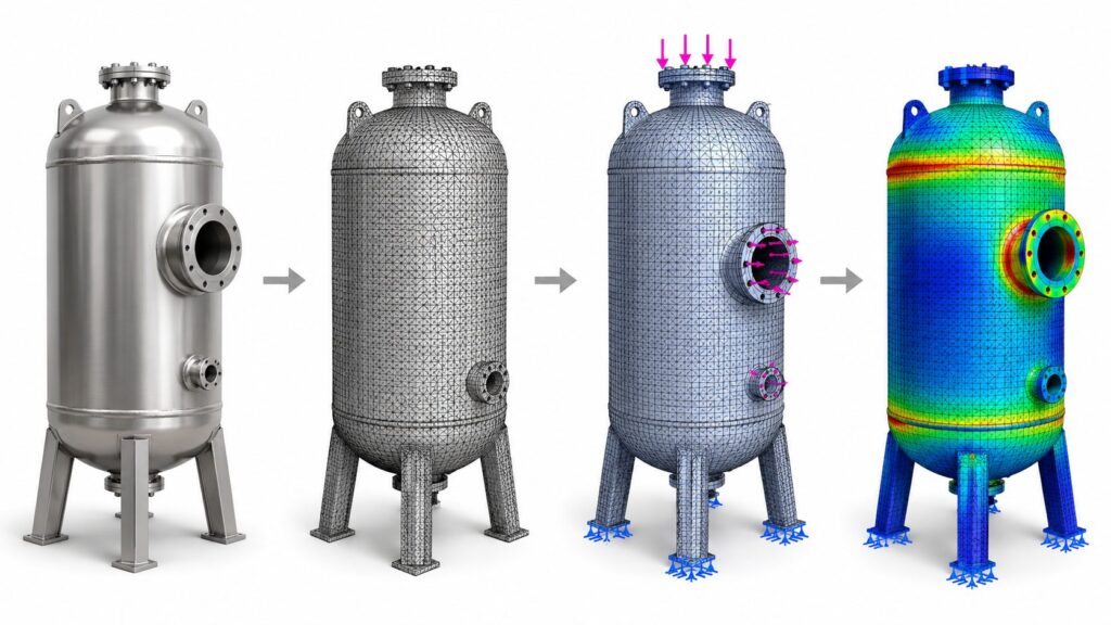
Figure: The FEA process in one image: a pressure vessel moves from raw CAD geometry, to a meshed model, to applied loads and supports, to a final stress contour showing exactly where the design is most at risk. CORE DEFINITIONFinite Element Analysis, or FEA, is a computational method that predicts how a physical part will behave under real-world load — stress, deflection, vibration, or heat — before it’s ever manufactured. It works by breaking a 3D model into thousands of small connected elements, applying the loads and constraints the part will actually see in service, and solving the underlying structural equations for each element to reconstruct a full-field picture of stress and displacement across the geometry. Most engineering teams have heard of FEA. Fewer can say precisely what it answers, what it costs to skip, or which of its several distinct flavors their part actually needs. That confusion is expensive: parts get over-engineered out of caution, or under-tested and shipped into a field failure that a two-day simulation pass would have caught. This article walks through how FEA actually works, the four analysis types that cover almost every real-world question, and a direct answer to when it’s worth running — and when it isn’t. How FEA Actually Works Every FEA study follows the same basic sequence, shown in the four-stage image above: The output isn’t a single pass/fail number — it’s a complete map of where a part is over-built, where it’s marginal, and where it will actually fail first. That last part matters: field failures rarely happen where engineers expect, and that’s usually because the load path wasn’t obvious from the CAD model alone. The Many Types of FEA Engineers Actually Run “FEA” isn’t one analysis — it’s a large family of methods, each answering a different question about the same part. The six below are the ones that come up most often in real product programs, shown on real results, followed by several more specialized types worth knowing. Static Structural Analysis (Single Worst-Case Load) Checks whether a part survives its maximum expected load — a drop, a lift point, a peak operating pressure — without yielding, buckling, or fracturing. This is the baseline FEA study almost every structural part goes through at least once, typically reported as a Von Mises stress contour against the material’s yield limit. Figure: Von Mises stress contour on a welded steel equipment frame, ranging from 0 to 400 MPa, with mass elements and rigid RBE2 connections shown at mounting points Fatigue Analysis (Repeated Cyclic Load) Checks whether a part survives millions of smaller, repeated load cycles over its service life. Most real-world structural failures happen this way — well below the load that would break the part in a single event — which is why fatigue is treated as a separate study from static strength. Orthopedic implants, springs, and rotating components are classic fatigue-critical parts. Figure: Stress mesh on an orthopedic bone plate implant with screws, showing a concentrated high-stress region in red and orange at the plate’s narrowest section Modal / Vibration Analysis (Natural Frequency & Resonance) Identifies a part’s natural resonant frequencies and mode shapes, so engineers can confirm it won’t resonate with vibration sources it will encounter in service — a motor, a road surface, a pump. This chassis result shows its first bending mode at 26.31 Hz; if an engine or road input sits near that frequency, the structure would need reinforcement. Figure: Displacement contour of a vehicle chassis frame at its first natural frequency of 26.31 Hz, showing peak displacement in red at the rear structure Thermal-Structural Analysis (Heat & Stress Coupled) Evaluates stress caused by temperature-driven expansion, contraction, and thermal gradients — critical for pressure vessels, dissimilar-material assemblies, and heat-generating components mounted to structural housings. The repeating stress bands here trace back to internal stiffening rings resisting thermal and pressure loading together. Figure: Thermal-structural stress banding on a horizontal pressure vessel, showing repeating red and blue stress bands from internal stiffening rings and temperature gradients Impact / Crash Analysis (Nonlinear, Transient Event) Simulates a real dynamic event — a frontal collision, a drop, a sudden impact — millisecond by millisecond, capturing large deformation, material failure, and contact between parts as they crush. It’s a heavier, more specialized study than the analyses above, reserved for structures where occupant or operator safety depends on exactly how the part deforms under a single extreme event. Figure: Frontal impact crash simulation of a light utility vehicle chassis at 48 km/h, with color-coded displacement magnitude and a seven-frame crash progression timeline Those six cover most of what a product development program will ever need — but the family goes further. Depending on the part and the risk it carries, an engineer may also reach for: Specialized FEA Analyses Across Disciplines Analysis Type & Focus What It Evaluates Buckling Analysis (Structural Stability) Predicts the load at which a slender or thin-walled part suddenly loses stability and collapses sideways, rather than failing by yielding — critical for columns, panels, and shells. Contact & Nonlinear Analysis (Parts in Contact) Models large deformation, sliding, gaps, and friction between mating parts — press fits, bolted joints, snap fits — where behavior isn’t a simple straight-line relationship between load and deflection. Topology Optimization (Design Generation) Lets the solver remove material algorithmically from a design space, generating the lightest structure that still meets stiffness and strength targets — common in weight-critical aerospace and automotive parts. Fatigue Crack Growth (Existing Cracks) Predicts how quickly an existing flaw or crack will propagate under cyclic loading, used to set inspection intervals for safety-critical structures where a crack can’t always be avoided entirely. Random Vibration Analysis (Broadband Vibration) Evaluates response to vibration that isn’t a single frequency but a statistical spectrum, such as road input or shipping and transport loads, common in automotive and aerospace qualification. Composite Laminate Analysis (Layered Materials) Analyzes stress ply-by-ply through a layered composite structure, checking for fiber failure, matrix cracking, and delamination between layers under load. Fluid-Structure Interaction