
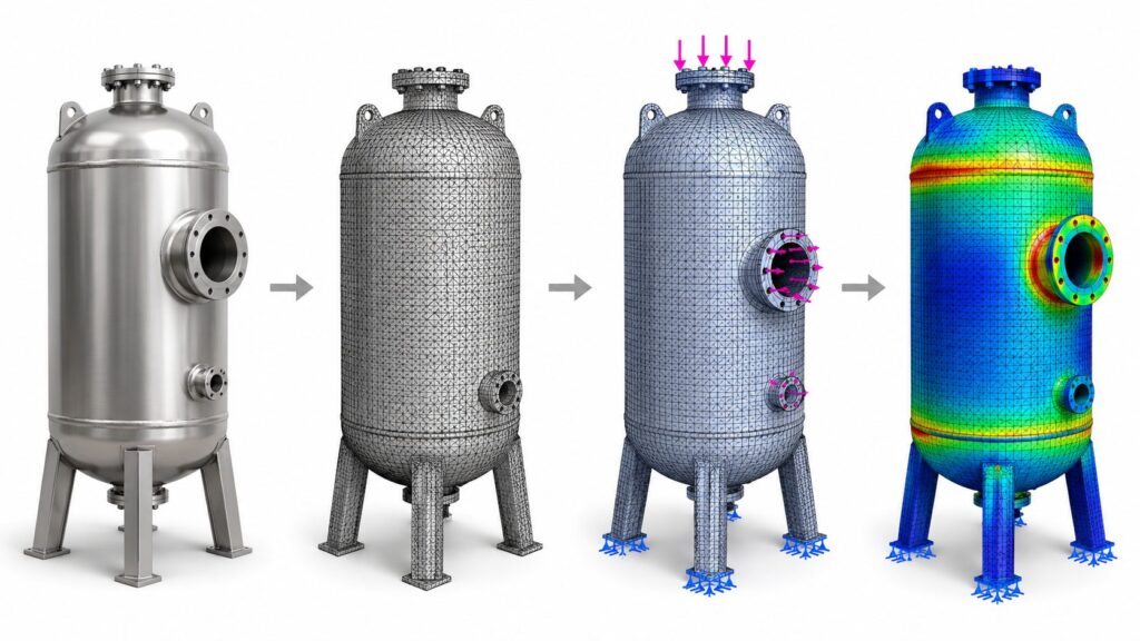
Figure: The FEA process in one image: a pressure vessel moves from raw CAD geometry, to a meshed model, to applied loads and supports, to a final stress contour showing exactly where the design is most at risk.
| CORE DEFINITION Finite Element Analysis, or FEA, is a computational method that predicts how a physical part will behave under real-world load — stress, deflection, vibration, or heat — before it’s ever manufactured. It works by breaking a 3D model into thousands of small connected elements, applying the loads and constraints the part will actually see in service, and solving the underlying structural equations for each element to reconstruct a full-field picture of stress and displacement across the geometry. |
Most engineering teams have heard of FEA. Fewer can say precisely what it answers, what it costs to skip, or which of its several distinct flavors their part actually needs. That confusion is expensive: parts get over-engineered out of caution, or under-tested and shipped into a field failure that a two-day simulation pass would have caught. This article walks through how FEA actually works, the four analysis types that cover almost every real-world question, and a direct answer to when it’s worth running — and when it isn’t.
How FEA Actually Works
Every FEA study follows the same basic sequence, shown in the four-stage image above:
- Meshing — the CAD geometry is divided into thousands to millions of small elements (tetrahedral, hexahedral, or shell elements depending on the geometry), each connected at shared nodes.
- Material assignment — real material properties are applied: yield strength, elastic modulus, Poisson’s ratio, fatigue curves, or thermal conductivity, depending on what’s being solved.
- Boundary conditions — the model is told how the part is actually held and loaded in service: fixed mounting points, applied forces or pressures, contact between mating parts, thermal loads.
- Solving — the solver assembles and solves a large system of equations describing how every element deforms and interacts with its neighbors under the applied conditions.
- Post-processing — results are reconstructed as full-field stress, strain, deflection, or temperature maps, checked against material limits and safety factors.
The output isn’t a single pass/fail number — it’s a complete map of where a part is over-built, where it’s marginal, and where it will actually fail first. That last part matters: field failures rarely happen where engineers expect, and that’s usually because the load path wasn’t obvious from the CAD model alone.
The Many Types of FEA Engineers Actually Run
“FEA” isn’t one analysis — it’s a large family of methods, each answering a different question about the same part. The six below are the ones that come up most often in real product programs, shown on real results, followed by several more specialized types worth knowing.
Static Structural Analysis (Single Worst-Case Load)
Checks whether a part survives its maximum expected load — a drop, a lift point, a peak operating pressure — without yielding, buckling, or fracturing. This is the baseline FEA study almost every structural part goes through at least once, typically reported as a Von Mises stress contour against the material’s yield limit.
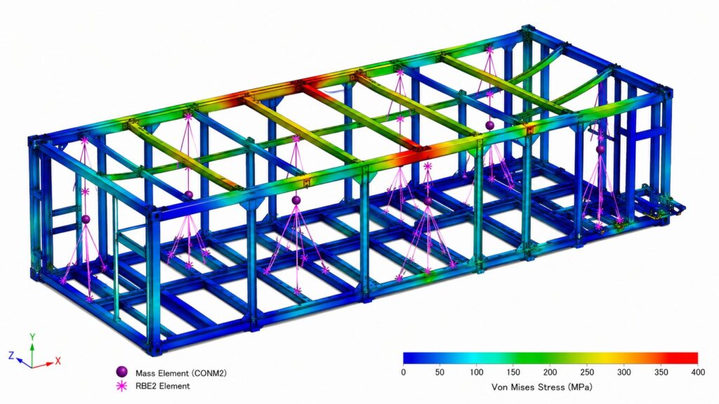
Figure: Von Mises stress contour on a welded steel equipment frame, ranging from 0 to 400 MPa, with mass elements and rigid RBE2 connections shown at mounting points
Fatigue Analysis (Repeated Cyclic Load)
Checks whether a part survives millions of smaller, repeated load cycles over its service life. Most real-world structural failures happen this way — well below the load that would break the part in a single event — which is why fatigue is treated as a separate study from static strength. Orthopedic implants, springs, and rotating components are classic fatigue-critical parts.
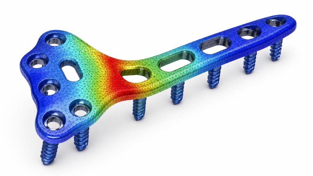
Figure: Stress mesh on an orthopedic bone plate implant with screws, showing a concentrated high-stress region in red and orange at the plate’s narrowest section
Modal / Vibration Analysis (Natural Frequency & Resonance)
Identifies a part’s natural resonant frequencies and mode shapes, so engineers can confirm it won’t resonate with vibration sources it will encounter in service — a motor, a road surface, a pump. This chassis result shows its first bending mode at 26.31 Hz; if an engine or road input sits near that frequency, the structure would need reinforcement.
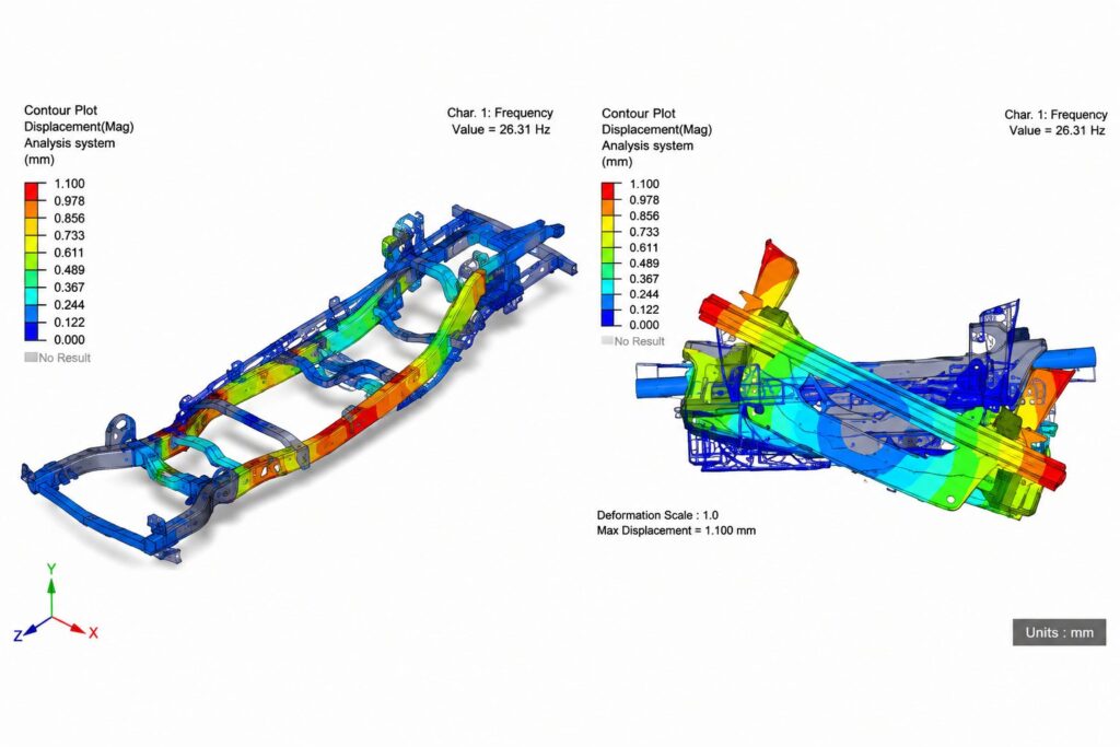
Figure: Displacement contour of a vehicle chassis frame at its first natural frequency of 26.31 Hz, showing peak displacement in red at the rear structure
Thermal-Structural Analysis (Heat & Stress Coupled)
Evaluates stress caused by temperature-driven expansion, contraction, and thermal gradients — critical for pressure vessels, dissimilar-material assemblies, and heat-generating components mounted to structural housings. The repeating stress bands here trace back to internal stiffening rings resisting thermal and pressure loading together.
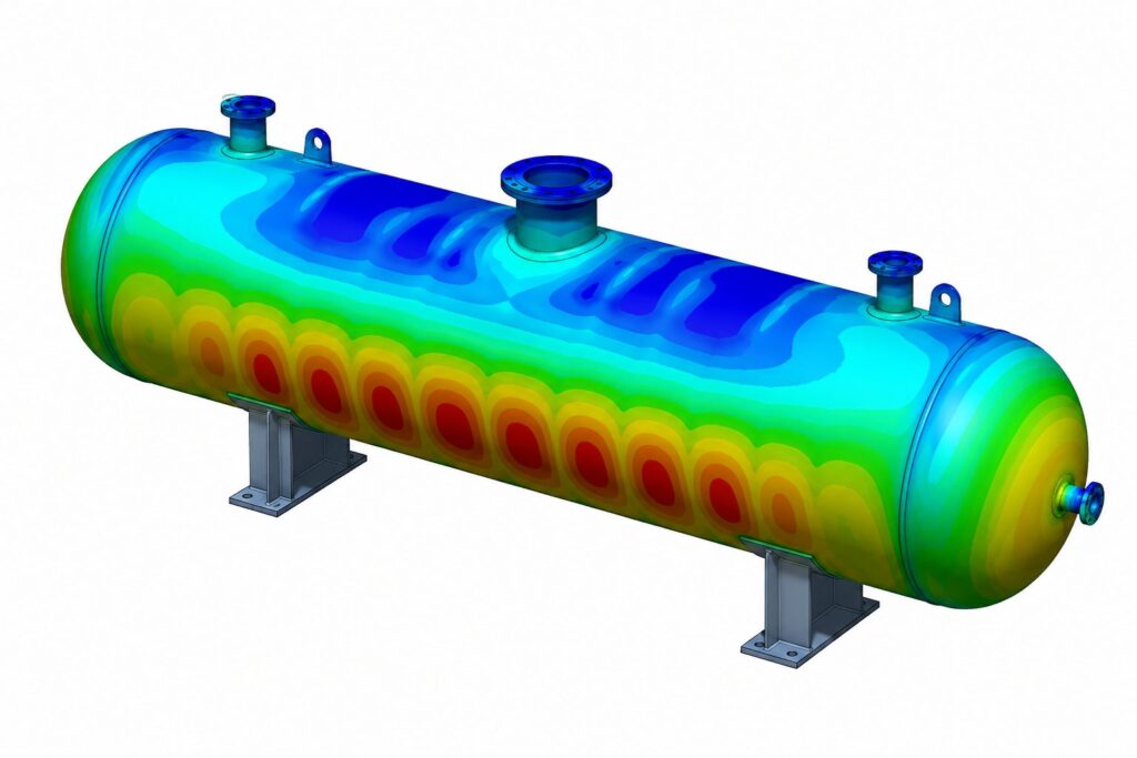
Figure: Thermal-structural stress banding on a horizontal pressure vessel, showing repeating red and blue stress bands from internal stiffening rings and temperature gradients
Impact / Crash Analysis (Nonlinear, Transient Event)
Simulates a real dynamic event — a frontal collision, a drop, a sudden impact — millisecond by millisecond, capturing large deformation, material failure, and contact between parts as they crush. It’s a heavier, more specialized study than the analyses above, reserved for structures where occupant or operator safety depends on exactly how the part deforms under a single extreme event.
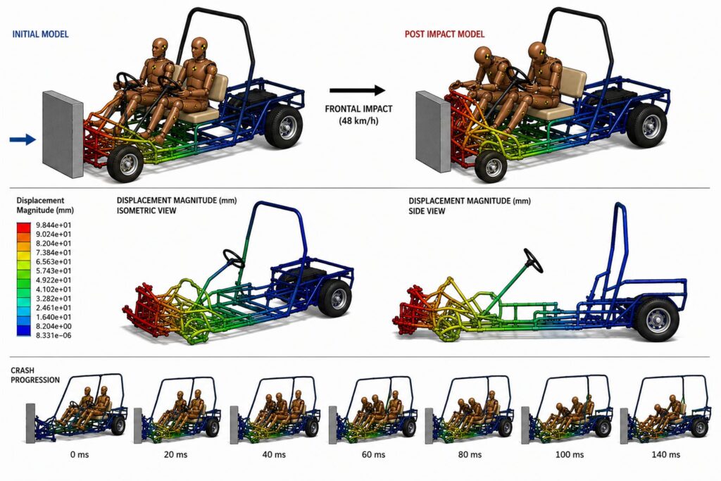
Figure: Frontal impact crash simulation of a light utility vehicle chassis at 48 km/h, with color-coded displacement magnitude and a seven-frame crash progression timeline
Those six cover most of what a product development program will ever need — but the family goes further. Depending on the part and the risk it carries, an engineer may also reach for:
Specialized FEA Analyses Across Disciplines
| Analysis Type & Focus | What It Evaluates |
| Buckling Analysis (Structural Stability) | Predicts the load at which a slender or thin-walled part suddenly loses stability and collapses sideways, rather than failing by yielding — critical for columns, panels, and shells. |
| Contact & Nonlinear Analysis (Parts in Contact) | Models large deformation, sliding, gaps, and friction between mating parts — press fits, bolted joints, snap fits — where behavior isn’t a simple straight-line relationship between load and deflection. |
| Topology Optimization (Design Generation) | Lets the solver remove material algorithmically from a design space, generating the lightest structure that still meets stiffness and strength targets — common in weight-critical aerospace and automotive parts. |
| Fatigue Crack Growth (Existing Cracks) | Predicts how quickly an existing flaw or crack will propagate under cyclic loading, used to set inspection intervals for safety-critical structures where a crack can’t always be avoided entirely. |
| Random Vibration Analysis (Broadband Vibration) | Evaluates response to vibration that isn’t a single frequency but a statistical spectrum, such as road input or shipping and transport loads, common in automotive and aerospace qualification. |
| Composite Laminate Analysis (Layered Materials) | Analyzes stress ply-by-ply through a layered composite structure, checking for fiber failure, matrix cracking, and delamination between layers under load. |
| Fluid-Structure Interaction (FSI) (Fluid + Structure) | Fully couples a CFD flow solution with an FEA structural model so each affects the other in real time — used where a flexible structure deforms enough to change the flow around it, like a valve or a flexible blade. |
| Drop Test Simulation (Sudden Shock) | Predicts stress and displacement from a short-duration shock event, such as a handheld product or a shipped package hitting the ground, used to validate packaging and enclosure design. |
In practice, most product programs need static structural analysis by default, fatigue analysis for anything that sees repeated operational cycles, modal analysis for anything near a vibration source, and thermal-structural analysis wherever temperature and load act on a part together. The more specialized types above get pulled in as the part, the risk, or the regulatory requirement calls for them.
| WHEN DO YOU NEED FEA — AND WHEN CAN YOU SKIP IT?WHEN TO RUN FEA: • The part carries meaningful structural or thermal load • It sees repeated cycling in service (fatigue risk) • Tooling or manufacturing commitment is expensive to reverse • The design is a new geometry with no field track record • A similar part has failed unexpectedly before • Weight or material reduction is a design goal and margins matterWHEN YOU CAN SKIP IT: • The part is lightly loaded with large, obvious margin • It’s a well-precedented design already proven in the field • Failure consequence is low — cosmetic or easily replaceable • A simple hand calculation clearly bounds the worst case • The part is a standard, catalog-sourced component |
What an FEA Deliverable Actually Looks Like
A useful FEA report is more than a colorful stress plot. At minimum, it should include:
- A stated set of assumptions — the loads, constraints, and material data used, so results can be trusted and defended in a design review
- Full-field stress and displacement contours — showing exactly where a part is highest-loaded, not just a single pass/fail number
- A calculated safety factor — the margin between predicted stress and the material’s allowable limit at the worst-case location
- Mesh convergence evidence — proof that results have stabilized and aren’t an artifact of a mesh that’s too coarse
- A design recommendation — where to add material, remove it, change a fillet radius, or reinforce a mounting point
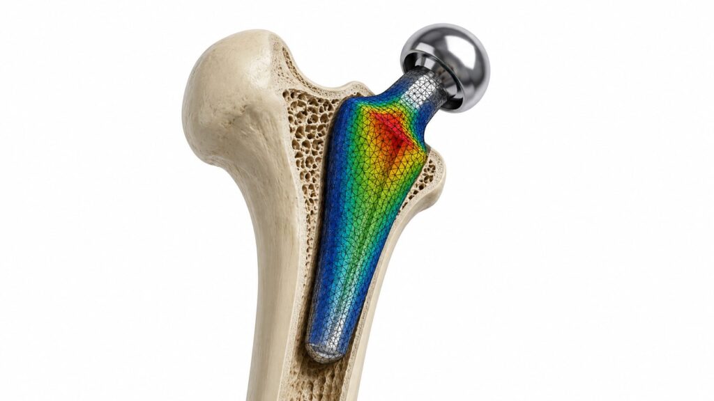
Figure: A real FEA deliverable ties a stress contour directly back to a design decision — here, a hip implant stem showing peak stress concentrated at the neck-to-stem transition, the exact region a geometry revision would target.
Without the assumptions and convergence check, a stress plot is just a picture. The value of FEA is in the engineering judgment applied around the numbers — knowing which load case actually governs, and what a marginal safety factor means for how the part will really be used.
Where FEA Fits Into a Full Development Workflow
FEA rarely stands alone. Structural results often feed back into product design decisions before tooling — a marginal safety factor might mean a fillet redesign, not a full material upgrade. And simulation predictions are only as trustworthy as their correlation to reality, which is why FEA findings are typically validated against physical testing before a design is finalized.
Where a part sees both fluid and structural loads — a pump housing, a pressure vessel, a heat exchanger bracket — FEA is frequently run as a coupled analysis, with pressure and thermal results from a CFD simulation applied directly as the load case on the structural model.
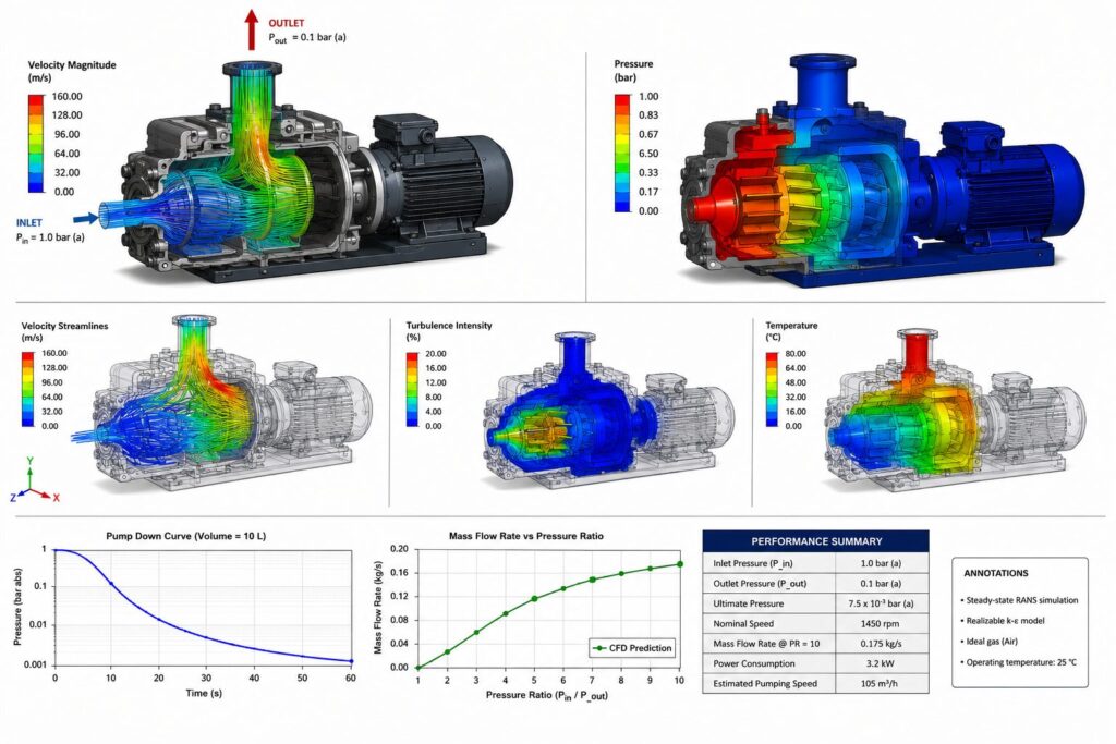
Figure: Pressure and temperature fields calculated by CFD, like this pump analysis, are a common input load case for a downstream FEA structural model — see ourCFD explainerfor how that simulation is built.
The Standards FEA Results Get Checked Against
A stress plot on its own proves nothing — it earns credibility by being checked against a recognized code, and by following a documented Verification & Validation (V&V) process. ASME V&V 10 is the governing standard for exactly that: it defines how to verify that an FEA model is solving its equations correctly, and how to validate that those equations represent physical reality, before a result is trusted for a design decision. Beyond that general V&V framework, most industries layer on their own design codes and qualification standards. Here are the ones that come up most often:
Verification & Validation
- ASME V&V 10: Guide for Verification and Validation in Computational Solid Mechanics — the core framework for trusting an FEA result.
- ASME V&V 10.1: An illustrative worked example applying the V&V 10 framework to a real structural problem.
- NAFEMS Guidelines: Independent best-practice benchmarks for mesh quality, convergence, and result credibility.
Pressure Equipment & Process
- ASME BPVC Section VIII, Div. 2: Design-by-analysis rules for pressure vessels — the primary code an FEA thermal-structural vessel study is checked against.
- API 579-1 / ASME FFS-1: Fitness-for-Service assessment for equipment with known flaws, corrosion, or damage.
- API 610 / API 617: Mechanical design requirements for centrifugal pumps and compressors, including allowable vibration and casing stress.
- API 6A / API 16A: Design and testing requirements for wellhead, drilling, and production equipment.
Environmental, Shock & Vibration
- MIL-STD-810G / 810H: Environmental engineering test methods — shock, random vibration, thermal cycling — widely used to define FEA load cases for defense and rugged industrial equipment.
- IEC 60068-2: Environmental testing for electronics, including shock and vibration test severities used as FEA boundary conditions.
- SAE J1455: Environmental durability standard for heavy-duty truck electrical and electronic equipment.
Medical Devices & Implants
- ASTM F2996: Standard practice for finite element analysis of non-modular metallic orthopedic hip femoral stems — a code written specifically for FEA.
- ISO 7206-4 / 7206-6: Fatigue testing requirements for hip implant stems, used to validate FEA fatigue predictions physically.
- ASTM F1717 / F1798: Fatigue and static test methods for spinal implant constructs.
- ISO 14708: General safety requirements for active implantable medical devices.
Structural Steel, Welded Frames & Containers
- AWS D1.1: Structural welding code for steel, governing allowable weld stress used in static structural FEA of welded frames.
- Eurocode 3 (EN 1993): Design of steel structures, including buckling and fatigue verification rules.
- AISC 360: Specification for structural steel buildings, used for allowable stress and stability checks in North America.
- IBC (International Building Code): Governs structural and load requirements for buildings and permanent structures, referenced when equipment frames, enclosures, or supports are treated as building structures.
- ASCE 7: Minimum Design Loads and Associated Criteria for Buildings and Other Structures — the source of wind, seismic, snow, and live load cases applied to structural and equipment-support FEA models in the US.
- ISO 1496 / CSC: Structural design and testing requirements for freight containers, including the stacking and racking loads used as FEA boundary conditions for container-style frames.
Automotive Safety & Crashworthiness
- FMVSS 208 / 216: US federal crash safety standards for occupant protection and roof crush resistance, common targets for impact FEA.
- Euro NCAP Protocols: European crash test rating protocols, frequently used to define FEA impact load cases and pass criteria.
- SAE J211: Instrumentation and data-processing standard for crash test measurement, used to correlate FEA against physical crash results.
Wind, Offshore & Marine
- IEC 61400-1: Design requirements for wind turbines, including structural and fatigue load cases.
- API RP 2A-WSD: Planning, design, and construction of fixed offshore platforms.
- DNV-ST-0126: DNV standard for structural design of wind turbine support structures.
The right code depends entirely on the part and its industry — an FEA report that cites the wrong standard, or none at all, is a report that can’t be defended in a design review or an audit. Matching the analysis to the applicable code is part of scoping the work correctly, before the first mesh is ever generated.
Where FEA Gets Used Across Industries
A cross-section of the industries and part types where structural simulation is standard practice, not optional.
Medical Devices & Implants
Figure: Medical Devices & Implants structural simulation model
Automotive & Off-Highway
Figure: Automotive & Off-Highway structural simulation model
Pressure Equipment & Process
Figure: Pressure Equipment & Process structural simulation model
Industrial & Heavy Equipment
Figure: Industrial & Heavy Equipment structural simulation model
Automotive Safety & Crashworthiness
Figure: Automotive Safety & Crashworthiness structural simulation model
Orthopedics & Biomechanics
Figure: Orthopedics & Biomechanics structural simulation model
Frequently Asked Questions (FAQ)
Q: What is FEA in simple terms?
A: Finite Element Analysis (FEA) is a computational method that predicts how a physical part or assembly will respond to real-world loads, such as force, pressure, vibration, or heat, by breaking the geometry into thousands of small elements and solving the governing structural equations for each one.
Q: What is the difference between static and fatigue FEA?
A: Static structural analysis checks whether a part survives a single worst-case load without yielding or failing. Fatigue analysis checks whether the part survives millions of smaller, repeated load cycles over its service life, since parts often fail from cumulative cyclic stress well below the load that would break them once.
Q: How accurate is FEA compared to physical testing?
A: A properly validated FEA model, with correct material properties, mesh density, and boundary conditions, typically predicts stress and deflection within a few percent of physical test results. Accuracy depends heavily on modeling assumptions, which is why FEA results are best used alongside targeted physical testing rather than as a full replacement for it.
Q: Do I need FEA for every part I design?
A: No. FEA is worth running when a part carries meaningful structural load, sees repeated cycling, involves an expensive tooling commitment, or has failed unexpectedly in the field. Low-load, low-consequence, or already well-precedented parts often do not need a dedicated simulation pass.
Q: What is Von Mises stress and why does it show up on every FEA plot?
A: Von Mises stress is a single calculated value that combines all the individual stress components at a point into one number, used to predict whether a ductile metal will yield under combined loading. It’s the standard contour plotted on FEA results because it gives a direct, single-number comparison against a material’s yield strength at every point in the model.
Q: Can FEA and CFD results be combined?
A: Yes. In a coupled analysis, pressure and thermal loads calculated by a CFD simulation are applied directly onto an FEA structural model, which is standard practice for pressure vessels, pump housings, heat exchangers, and any part where fluid or thermal loading drives structural stress.
Q: What is ASME V&V 10 and why does it matter for FEA?
A: ASME V&V 10 is the Guide for Verification and Validation in Computational Solid Mechanics. It defines the process for verifying that an FEA model solves its underlying equations correctly and validating that those equations represent physical reality, which is the recognized framework for establishing that an FEA result can be trusted for a design decision.
Q: What standard governs FEA of pressure vessels?
A: ASME Boiler and Pressure Vessel Code, Section VIII, Division 2, provides design-by-analysis rules that are the primary code an FEA-based pressure vessel structural study is checked against, often alongside API 579-1 / ASME FFS-1 for fitness-for-service assessments of equipment with existing damage or corrosion.
Q: Is there an FEA-specific standard for orthopedic implants?
A: Yes. ASTM F2996 is a standard practice written specifically for finite element analysis of non-modular metallic orthopedic hip femoral stems, typically used alongside physical fatigue testing per ISO 7206-4 and 7206-6 to validate the simulation results.
Q: What standards apply to FEA of structural frames and containers?
A: Structural steel frames and equipment supports are commonly checked against AWS D1.1 for welded connections and AISC 360 or Eurocode 3 for member and stability design. Where a frame is treated as a building structure, the International Building Code (IBC) and ASCE 7 supply the wind, seismic, and live load cases used as FEA boundary conditions. Freight and shipping containers are additionally checked against ISO 1496 and CSC stacking and racking requirements.
Q: What software or standards does FEA follow?
A: FEA is a numerical method, not a single piece of software, and results are typically checked against relevant design codes and standards for the industry, such as ASME, IEC, API, MIL-STD, IBC, ASCE 7, or automotive and aerospace-specific structural standards, depending on the application.