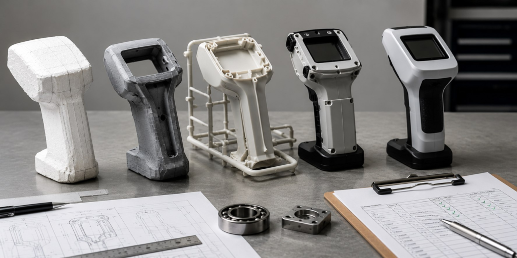
DFM vs DFA: What’s the Difference, and Why Your Product Needs Both
What Is DFM (Design for Manufacturing)? Design for Manufacturing is the practice of shaping a part’s geometry around the realities of the process that will make it — injection molding, CNC machining, sheet metal forming, die casting — instead of designing the geometry first and hoping a manufacturing process can catch up to it later. A DFM review looks at a single part and asks whether its features match what the intended process can actually produce reliably, at the tolerance the design calls for, at a cost the program can afford. That means checking wall thickness for uniformity, draft angle for mold release, rib geometry against the wall it’s attached to, hole depth-to-diameter ratios for machining, and bend radii against material and tooling limits. None of this is about whether the part looks right. It’s about whether the part as drawn can leave the factory floor without sink marks, warping, tool breakage, scrap, or a tooling change order. Figure: Wall thickness, draft angle, and rib geometry decided before tooling — not after the first shot. What Is DFA (Design for Assembly)? Design for Assembly is the practice of shaping a product — the full set of parts working together — around how efficiently and reliably a person or a machine can put it together. Where DFM asks questions about one part in isolation, DFA asks questions about the relationships between parts. A DFA review counts parts and fasteners, checks whether each part can only go together one correct way, checks insertion direction and access, and looks for opportunities to combine several parts into one. The guiding question is simple: does every part in this product need to exist separately, or could this assembly be simpler? DFA has a well-established methodology behind it — Boothroyd-Dewhurst analysis scores a design on theoretical minimum part count, handling time, and insertion time — but the underlying instinct predates any formal scoring system: fewer parts, fewer fasteners, fewer ways to get it wrong on the line. Figure: Fewer parts and fewer fastener types mean fewer chances to assemble it wrong. DFM vs DFA: The Key Differences Both disciplines exist to remove cost and risk before it reaches the factory floor, but they optimize for different things, at different scales, and they surface different failure modes when skipped. DFM — Design for Manufacturing DFA — Design for Assembly Unit of analysis A single part The full product, as a set of parts Core question Can this part be made reliably, at this tolerance, by this process? Can this product be put together quickly, correctly, and only one way? Typical checks Wall thickness, draft angle, rib geometry, tolerances, tool access Part count, fastener count, insertion direction, symmetry, poka-yoke Failure if skipped Scrap, sink marks, tool breakage, warping, tooling rework Slow assembly, incorrect builds, rework at the line, warranty returns Who feels it The moldmaker, machinist, or fabricator The assembly technician or the end customer replacing/servicing the product Why You Need Both, Not Either/Or The trap is treating DFM and DFA as a checklist to run once, in sequence, rather than as two lenses applied to the same design at the same time. In practice, they pull on each other constantly. Consolidating two brackets into one part — a classic DFA win — can push wall thickness or rib geometry into territory that’s harder to mold, which is a DFM problem the DFA change just created. Adding draft angle to a part for moldability — a DFM fix — can change how it mates with its neighbor, which affects assembly force and insertion direction, a DFA concern. Reviewing the two separately means catching each fix’s side effect after the fact instead of before. DFM VS DFA COMPARISON MATRIXDFM ALONE GETS YOU: • Individually manufacturable parts • Lower per-part scrap and reject rate • A product that’s still slow or error-prone to build DFA ALONE GETS YOU: • Fast, low-error assembly • Fewer fasteners and touch points • Consolidated parts that may now be difficult or costly to mold or machine Run together, the two disciplines converge on the same target: a product that is both cheap to make part-by-part and fast to build as a whole — which is the actual cost driver a production program lives or dies by. Figure: Tolerance decided during DFM determines whether the DFA assembly step is a slide-fit or a fight. DFM in Practice: Three Manufacturing Processes DFM rules aren’t universal — they’re specific to the process making the part. A rule that protects an injection-molded housing can be irrelevant to a CNC-machined bracket. Three of the most common processes VYRSTA reviews against: Injection Molding Uniform wall thickness prevents sink marks and warping as plastic cools unevenly. Draft angle — typically 1 to 2 degrees minimum on vertical walls — lets the part release from the mold without dragging or scarring. Ribs should stay at 50 to 60 percent of the wall thickness they attach to, to avoid sink marks showing through the opposite face. CNC Machining Internal corners need a radius that matches an available cutting tool — a true sharp internal corner can’t be machined without EDM. Deep, narrow pockets increase cycle time and tool deflection risk. Hole depth beyond roughly four to five times the diameter starts to challenge standard drilling and hurts positional accuracy. Sheet Metal Bend radius has a practical minimum tied to material thickness and grain direction, below which the metal cracks at the bend. Features placed too close to a bend line distort during forming. Hole diameters too close to an edge or another hole risk tearing during punching. Figure: Internal fillets sized to an available cutting tool — the difference between one operation and a second EDM step. Tolerancing and GD&T: The Language That Actually Controls Fit A generic title-block tolerance — a blanket ±0.1 mm applied to every dimension on a drawing — is where most DFM/DFA reviews find their next problem. It assumes parts deviate only in straight-line distance. They don’t Manufactured features tilt, bow, warp, and rotate, and a linear tolerance has no way to describe any of that. Controlling how a part is actually allowed to vary — not just how big it’s allowed