
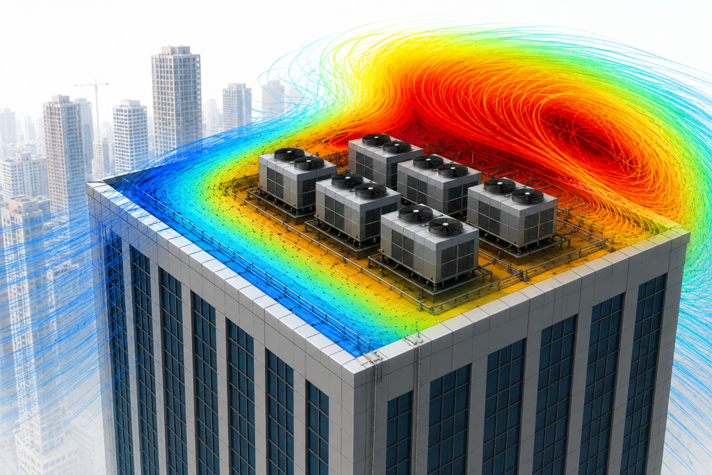
Figure: CFD thermal simulation of rooftop HVAC chiller units showing velocity streamlines and temperature distribution: identifying hot-air recirculation before construction.
| DIRECT ANSWER Computational Fluid Dynamics (CFD) is a numerical simulation method that predicts how air, liquid, pressure, and heat behave around and inside a product by solving the governing physics equations across a 3D digital model. It matters whenever airflow, cooling, liquid flow, or thermal behaviour affects your product’s performance, reliability, efficiency, or safety — because it finds problems like trapped heat or poor airflow before you cut any tooling. |
| KEY TAKE AWAYS EXECUTIVE SUMMARY: • CFD is a digital experiment: a 3D model is divided into a mesh of thousands to millions of cells, and a solver calculates velocity, pressure, temperature, and turbulence in each one. • It splits into two related questions: thermal simulation (does it overheat?) and flow/aerodynamic simulation (does air or fluid move where it needs to?). • Electronics enclosures, battery packs, HVAC/pump/valve systems, and aerodynamic products are the categories that consistently benefit. • CFD doesn’t replace physical testing — it eliminates weak design options early so physical testing validates a design that’s already been through several iterations. • CFD run after the CAD is frozen becomes documentation, not a design tool. Run early, it actively shapes the geometry. |
Most engineering teams have heard of CFD. Far fewer have a clear answer for when it’s worth commissioning versus when it’s overkill. This guide covers what CFD actually calculates, the product situations where it consistently pays for itself, and what a real engineering deliverable looks like — not just the colorful contour plots.
What CFD Actually Simulates
At its core, CFD is a digital experiment. Instead of building a physical prototype first, engineers create a 3D model of the product and divide it into a mesh — a network of thousands, often millions, of small computational cells that lets the software solve the governing equations of fluid motion and heat transfer across the entire geometry.
For every mesh cell, the solver calculates:
- Fluid velocity — how fast the fluid moves
- Pressure — and where it drops or builds
- Temperature and heat transfer rate
- Turbulence — irregular fluid motion
- Flow direction — including recirculation and separation
Together, these results build a complete picture of how air, liquid, or gas behaves inside and around a product — the same picture you’d otherwise only get by instrumenting a physical prototype.
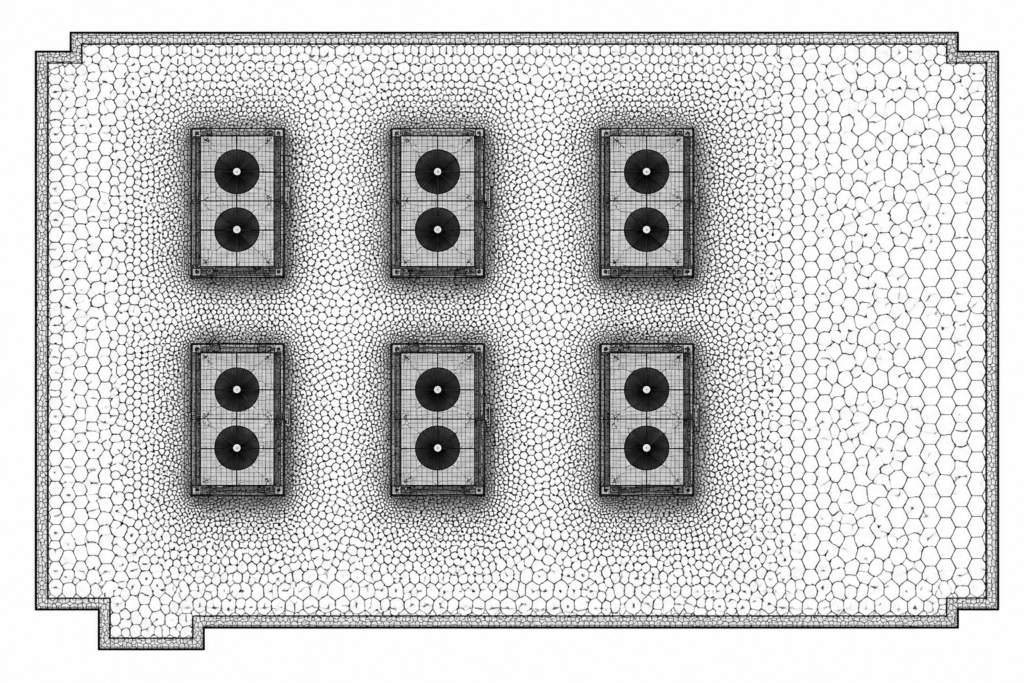
Figure: The mesh behind the picture: rooftop condenser units and their surrounding air domain broken into thousands of computational cells before the solver runs.
Thermal (Heat Transfer) Simulation
Thermal simulation focuses on how heat is generated, conducted, and dissipated within a product. It answers questions like: Will the electronics overheat? Does the enclosure trap heat? Is the heatsink sized correctly? Will battery temperatures stay within operating limits?
Many products also require conjugate heat transfer — solving heat transfer through solid components and the surrounding fluid simultaneously. This is more realistic than a solids-only or fluid-only model, because heat doesn’t stop at a component’s surface; it moves continuously between solid and fluid.
Flow & Aerodynamic Simulation
Flow simulation examines how fluids move through or around a product: Does airflow actually reach every cooling component? Is pressure loss too high inside a duct? Will turbulence reduce performance? How much drag does the enclosure create?
Thermal and flow simulation are frequently run together, because airflow directly governs cooling performance — you can’t accurately predict one without the other.
How a CFD Study Actually Runs
Every CFD project moves through the same six stages, regardless of product type. Knowing them makes it easier to scope a study and to see where the timeline and cost actually come from.
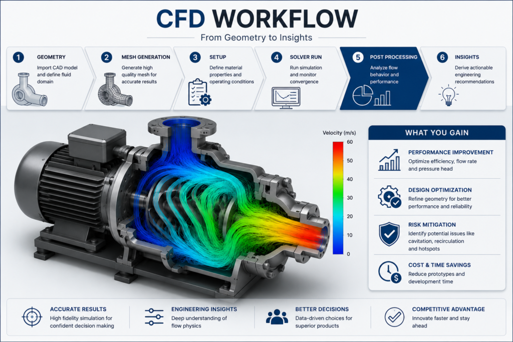
Figure: From geometry to insights: the six stages every CFD study passes through, shown here on a centrifugal pump colored by flow velocity.
1. Geometry — the CAD model is imported and the fluid domain (the air or liquid volume around and inside the part) is defined.
2. Mesh generation — the domain is divided into a high-quality mesh; mesh density and quality directly control result accuracy.
3. Setup — material properties and operating conditions (boundary conditions) are defined to match real-world use.
4. Solver run — the simulation runs and convergence is monitored to confirm the solution is stable and physically valid.
5. Post-processing — flow behavior and performance are analyzed through contour plots, streamlines, and quantified metrics.
6. Insights — results are translated into actionable engineering recommendations, not just images.
Done well, this workflow delivers performance improvement, design optimization, and early risk mitigation — catching cavitation, recirculation, or hotspots — while cutting the number of physical prototypes needed to get there.
Five Signs Your Product Needs CFD
Not every product needs CFD. These are the design situations that consistently justify it before hardware gets built.
1. Electronics that generate significant heat
A sealed enclosure can look fine in CAD yet trap hot air around a processor or power stage. After roughly 20 minutes of operation, temperatures climb enough to trigger thermal throttling or shorten component life. CFD finds these hot spots before a prototype exists, so ventilation, heatsink sizing, or component placement can still change.
2. Battery systems with cooling challenges
Battery packs depend on uniform temperature across cells. Poor cooling creates localized hot regions that accelerate cell ageing, cut performance, and raise safety risk. CFD maps airflow paths, coolant distribution, and cell-to-cell temperature variation before an expensive prototype pack gets assembled.
3. HVAC, pumps, valves, and fluid-handling equipment
Products that intentionally move air or liquid depend on efficient flow. A duct can introduce unnecessary pressure loss, a valve can create excessive turbulence, or a pump housing can trap a recirculation zone that quietly kills efficiency. CFD makes these hidden flow behaviors visible before manufacturing.
4. Aerodynamic products
Drones, automotive components, industrial equipment, outdoor electronics, and cooling fans are all exposed to external airflow. A housing that looks streamlined in CAD can still create separated flow that increases drag, vibration, or wind noise. CFD predicts this early enough for geometry changes to stay practical.
5. Products where prototype failures are expensive
Some fixes are cheap. Others mean redesigning tooling, modifying castings, rebuilding prototypes, or repeating compliance testing. If discovering a thermal or airflow problem after fabrication would delay the project or add real cost, CFD is risk reduction, not an optional exercise.
Where CFD Gets Used Across Industries
CFD isn’t tied to one product type — it applies anywhere airflow, liquid flow, or heat transfer affects performance, reliability, or safety. Three categories account for the bulk of day-to-day CFD work; the table below covers the fuller range of industries VYRSTA works across.
Embedded systems & enclosures (Electronics Cooling)
Airflow paths from intake fans across the PCB, heatsink, and power components to the exhaust vent — used to confirm a sealed or fan-cooled enclosure won’t throttle under sustained load.
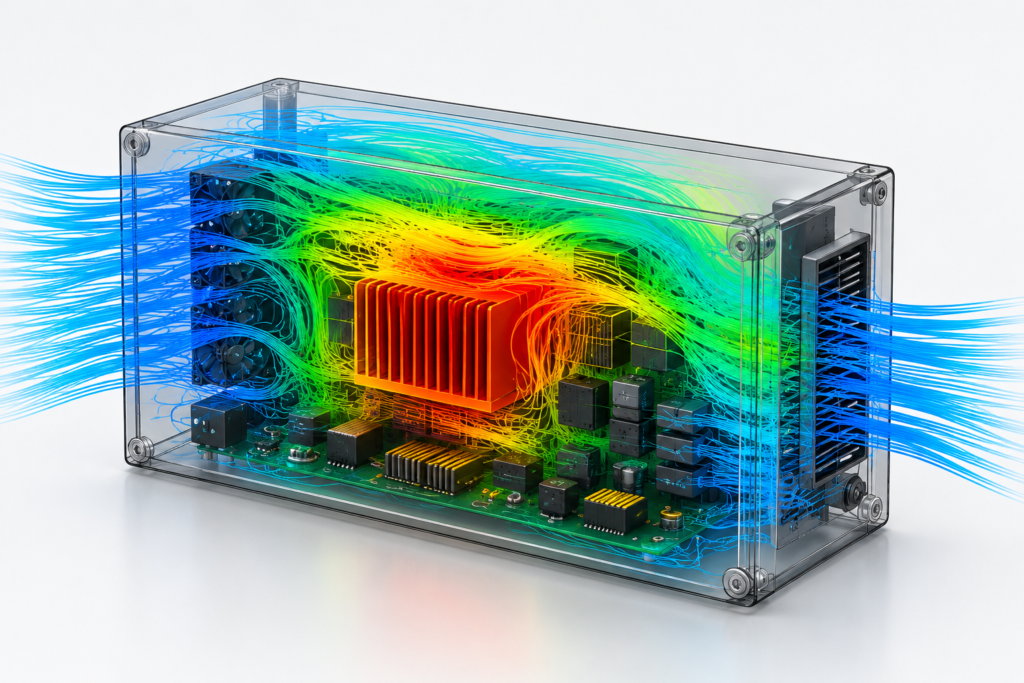
Figure: Electronics Cooling: Embedded systems & enclosures
Rooftop HVAC & building services (Architectural & Building Cooling)
Temperature and recirculation mapping around condenser arrays, ductwork, and rooftop plant — used to catch hot-air recirculation that quietly degrades chiller efficiency.
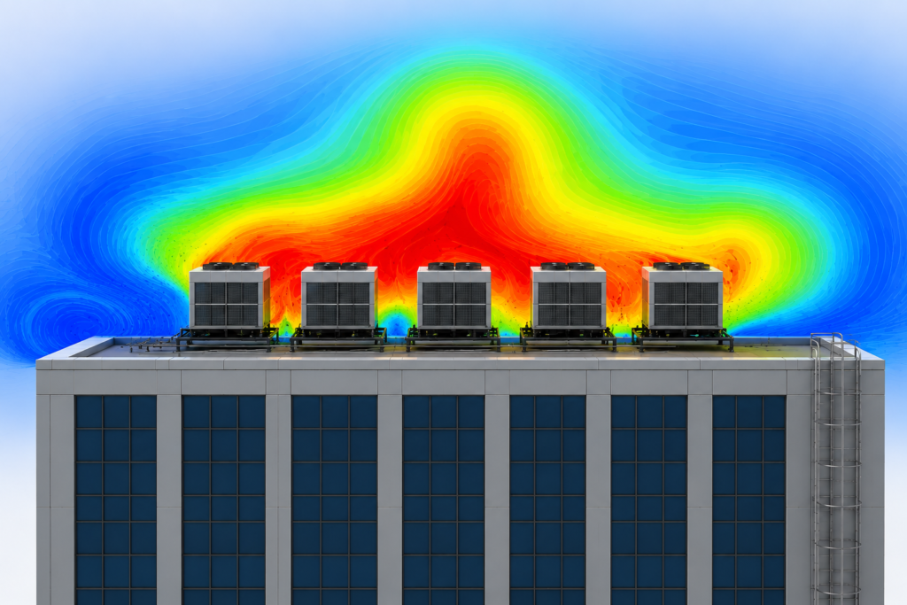
Figure: Architectural & Building Cooling: Rooftop HVAC & building services
Facility & data center thermal management (Data Center & Facility-Scale Cooling)
Large-scale streamline and temperature modeling across rooftop plant serving a facility or data hall — used to size cooling capacity and confirm units aren’t re-ingesting each other’s exhaust.
Figure: Data Center & Facility-Scale Cooling: Facility & data center thermal management
CFD by Industry
| Industry | Typical CFD focus | Example question CFD answers |
| Battery & energy storage | Cell-to-cell temperature uniformity, coolant plate design, thermal runaway propagation | Are all cells in the pack staying within their rated temperature band under fast charge? |
| Data centers & facility cooling | Hot/cold aisle containment, CRAC/CRAH airflow, rooftop plant recirculation | Is exhaust air from one cooling unit being re-ingested by the intake of another? |
| HVAC & building services | Duct pressure loss, diffuser placement, rooftop condenser layout | Does conditioned air actually reach every zone at the designed flow rate? |
| Medical devices | Respiratory and drug-delivery airflow, device cooling, biofluid flow | Does the device deliver consistent flow/dosage across its intended operating range? |
| Marine engineering | Hull hydrodynamics, engine room ventilation, ballast and cooling water systems | Is engine room airflow sufficient to keep equipment within thermal limits at sea? |
| Oil & gas / process equipment | Pipeline and separator flow, pressure drop across valves and manifolds, flare dispersion | Where does pressure loss concentrate across this piping network, and can it be reduced? |
| Mining & heavy industry | Underground ventilation, dust dispersion, equipment bay cooling | Does the ventilation network maintain safe air quality at every working face? |
| Robotics & automation | Motor and drive electronics cooling, actuator thermal limits | Will the motor stay within its thermal envelope across a full duty cycle? |
| Consumer & industrial electronics | Enclosure airflow, heatsink sizing, fan selection | Is the enclosure venting enough hot air to avoid thermal throttling? |
| Automotive & transportation | Underhood thermal management, external aerodynamics, cabin HVAC | How much does a given bodyline change affect drag or underhood cooling? |
| Aerospace & defense | External aerodynamics, environmental control systems, avionics cooling | Does the environmental control system maintain cabin conditions across the flight envelope? |
| Industrial equipment | Pump, valve, and compressor internal flow; cavitation and recirculation zones | Where in the housing does recirculation reduce pump efficiency? |
CFD vs. Physical Testing vs. Wind Tunnel Testing
CFD and physical testing answer the same engineering questions at different stages. CFD predicts behavior before hardware exists, so engineers can compare design alternatives and run “what-if” scenarios without manufacturing each variant. Physical testing — including wind tunnel testing where relevant — measures how the real product performs under controlled conditions, capturing manufacturing variation, material behavior, and environmental effects that a simulation may not fully represent. Neither replaces the other; the strongest process uses CFD to eliminate weak design options early and physical testing to validate the final design before production.
| Method | Best for | Limitation |
| CFD simulation | Comparing design alternatives early, before tooling exists; isolating cause of a flow or thermal issue | Accuracy depends on mesh quality, boundary conditions, and modeling assumptions |
| Physical bench testing | Validating a near-final design under real operating conditions | Captures only the configurations actually built and tested |
| Wind tunnel testing | Confirming external aerodynamic performance (drag, lift, noise) on a physical model | Expensive and slow to iterate against; usually reserved for late-stage validation |
How Accurate Is CFD Compared to Physical Testing?
CFD produces reliable engineering predictions when the problem is modeled correctly — but accuracy depends on several factors working together. Mesh quality determines how well complex geometry is represented. Boundary conditions — the known operating inputs such as inlet airflow, ambient temperature, flow rate, pressure, or heat generation — have to match real operating conditions, or the results diverge from reality. The physics models, material properties, and engineering assumptions selected all shape the outcome as well.
This is exactly why engineering teams pair CFD with physical validation: simulation guides design decisions early, and physical testing confirms the finished product behaves as predicted under real conditions.
What Happens When CFD Runs Separately From Design
A common industry workflow separates product design from simulation entirely. Mechanical designers finish the enclosure, freeze the CAD model, then hand it to a separate CFD specialist or an external vendor. The simulation may correctly flag overheating, poor airflow, or excessive pressure loss — but by that point the enclosure geometry, packaging constraints, and tooling are already largely fixed. The CFD report becomes documentation of a problem rather than a tool for solving it, because implementing the fix would mean a significant redesign.
Running CFD earlier changes the role simulation plays entirely. Instead of validating finished geometry, it actively shapes it — vents get repositioned, internal layouts optimized, materials reconsidered, and cooling strategies improved while the design is still flexible. That’s the integrated workflow behind VYRSTA’s CFD Engineering Services, where simulation informs design rather than reviewing it after the fact.
What a CFD Deliverable Actually Looks Like
A CFD project produces far more than colorful flow images. A complete engineering deliverable typically includes:
| DELIVERABLES FROM A PROFESSIONAL CFD STUDY Flow and thermal contour visualizations: Color maps of airflow velocity, pressure distribution, and temperature across the product, so hot spots, recirculation regions, and restricted flow paths are immediately visible. Design comparison studies: Side-by-side comparisons between design alternatives, showing how a proposed geometry change affects cooling, pressure loss, airflow distribution, or thermal performance. Engineering findings report: A written summary covering engineering assumptions, simulation setup, operating conditions, key observations, and identified risks. Engineering recommendations: Practical next steps — adjusting vent locations, modifying duct geometry, relocating a heat-generating component, changing material, or altering the cooling strategy — not just a list of problems. |
You’re not paying for simulation images. You’re paying for engineering decisions backed by quantified analysis.
Thermal and flow results from CFD frequently become the load case for a downstream FEA structural simulation — a pump housing or heat exchanger bracket, for example, needs both a fluid analysis and a stress analysis before the design is locked. And once simulation has shaped the geometry, a DFM/DFA review is what confirms that geometry is still manufacturable before tooling is committed.