
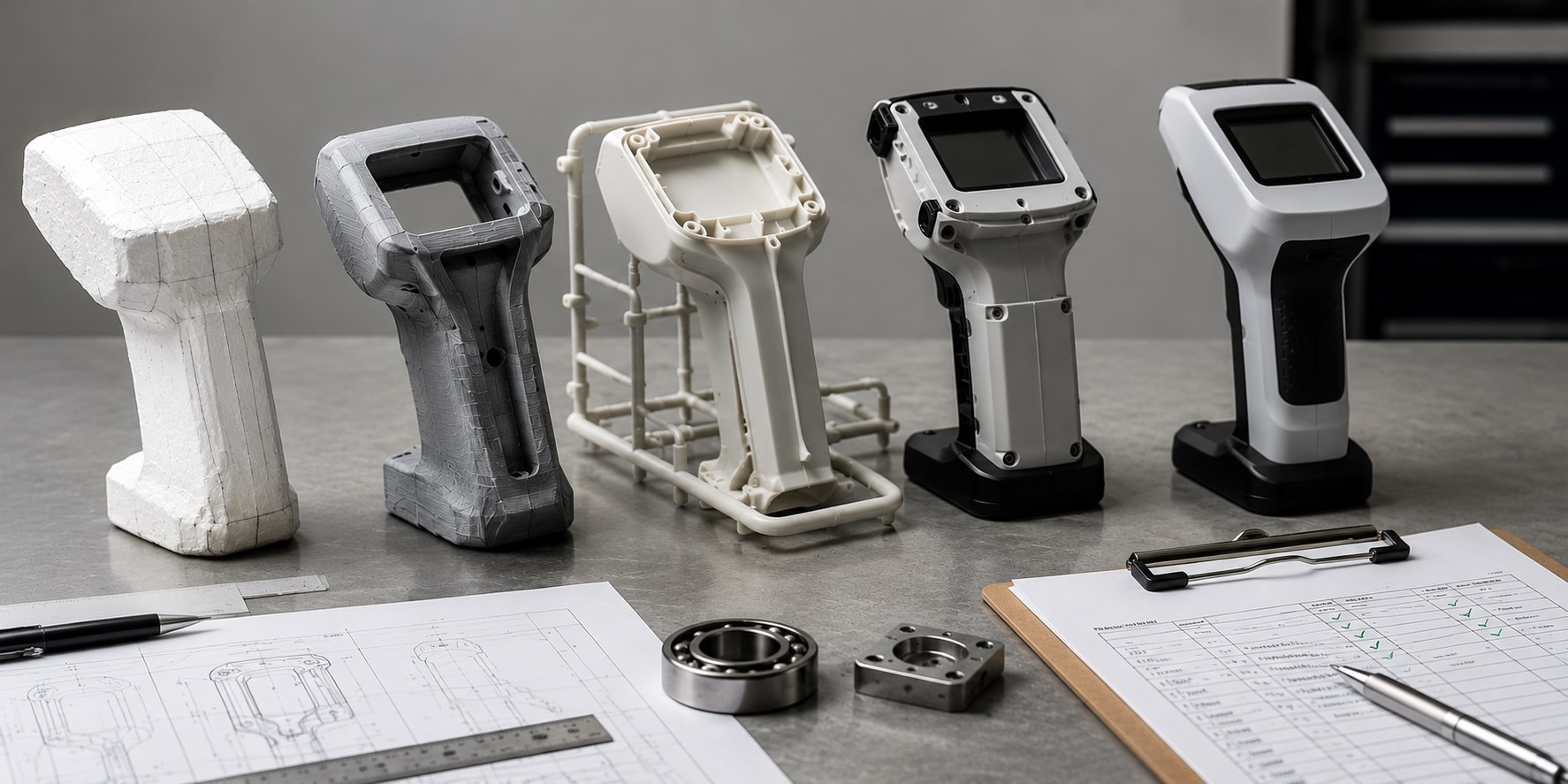
What Is DFM (Design for Manufacturing)?
Design for Manufacturing is the practice of shaping a part’s geometry around the realities of the process that will make it — injection molding, CNC machining, sheet metal forming, die casting — instead of designing the geometry first and hoping a manufacturing process can catch up to it later.
A DFM review looks at a single part and asks whether its features match what the intended process can actually produce reliably, at the tolerance the design calls for, at a cost the program can afford. That means checking wall thickness for uniformity, draft angle for mold release, rib geometry against the wall it’s attached to, hole depth-to-diameter ratios for machining, and bend radii against material and tooling limits.
None of this is about whether the part looks right. It’s about whether the part as drawn can leave the
factory floor without sink marks, warping, tool breakage, scrap, or a tooling change order.
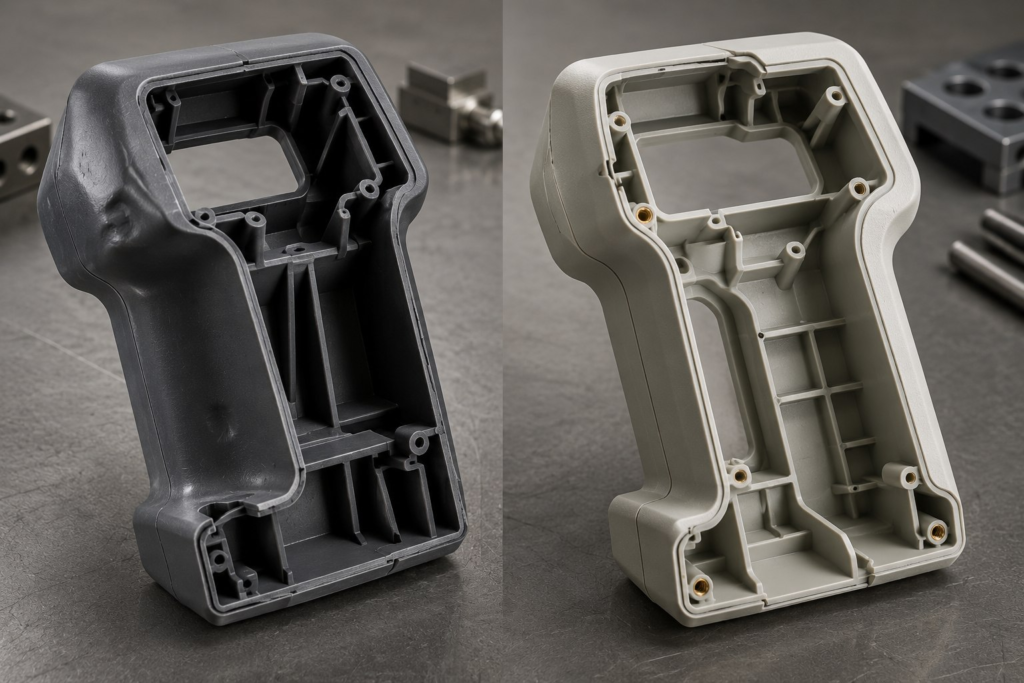
Figure: Wall thickness, draft angle, and rib geometry decided before tooling — not
after the first shot.
What Is DFA (Design for Assembly)?
Design for Assembly is the practice of shaping a product — the full set of parts working together — around how efficiently and reliably a person or a machine can put it together. Where DFM asks questions about one part in isolation, DFA asks questions about the relationships between parts.
A DFA review counts parts and fasteners, checks whether each part can only go together one correct way, checks insertion direction and access, and looks for opportunities to combine several parts into one. The guiding question is simple: does every part in this product need to exist separately, or could this assembly be simpler?
DFA has a well-established methodology behind it — Boothroyd-Dewhurst analysis scores a design on theoretical minimum part count, handling time, and insertion time — but the underlying instinct predates any formal scoring system: fewer parts, fewer fasteners, fewer ways to get it wrong on the line.
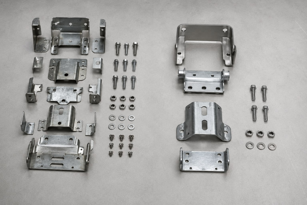
Figure: Fewer parts and fewer fastener types mean fewer chances to assemble it wrong.
DFM vs DFA: The Key Differences
Both disciplines exist to remove cost and risk before it reaches the factory floor, but they optimize for different things, at different scales, and they surface different failure modes when skipped.
| DFM — Design for Manufacturing | DFA — Design for Assembly | |
| Unit of analysis | A single part | The full product, as a set of parts |
| Core question | Can this part be made reliably, at this tolerance, by this process? | Can this product be put together quickly, correctly, and only one way? |
| Typical checks | Wall thickness, draft angle, rib geometry, tolerances, tool access | Part count, fastener count, insertion direction, symmetry, poka-yoke |
| Failure if skipped | Scrap, sink marks, tool breakage, warping, tooling rework | Slow assembly, incorrect builds, rework at the line, warranty returns |
| Who feels it | The moldmaker, machinist, or fabricator | The assembly technician or the end customer replacing/servicing the product |
Why You Need Both, Not Either/Or
The trap is treating DFM and DFA as a checklist to run once, in sequence, rather than as two lenses applied to the same design at the same time. In practice, they pull on each other constantly.
Consolidating two brackets into one part — a classic DFA win — can push wall thickness or rib geometry into territory that’s harder to mold, which is a DFM problem the DFA change just created. Adding draft angle to a part for moldability — a DFM fix — can change how it mates with its neighbor, which affects assembly force and insertion direction, a DFA concern. Reviewing the two separately means catching each fix’s side effect after the fact instead of before.
| DFM VS DFA COMPARISON MATRIXDFM ALONE GETS YOU: • Individually manufacturable parts • Lower per-part scrap and reject rate • A product that’s still slow or error-prone to build DFA ALONE GETS YOU: • Fast, low-error assembly • Fewer fasteners and touch points • Consolidated parts that may now be difficult or costly to mold or machine |
Run together, the two disciplines converge on the same target: a product that is both cheap to make part-by-part and fast to build as a whole — which is the actual cost driver a production program lives or dies by.
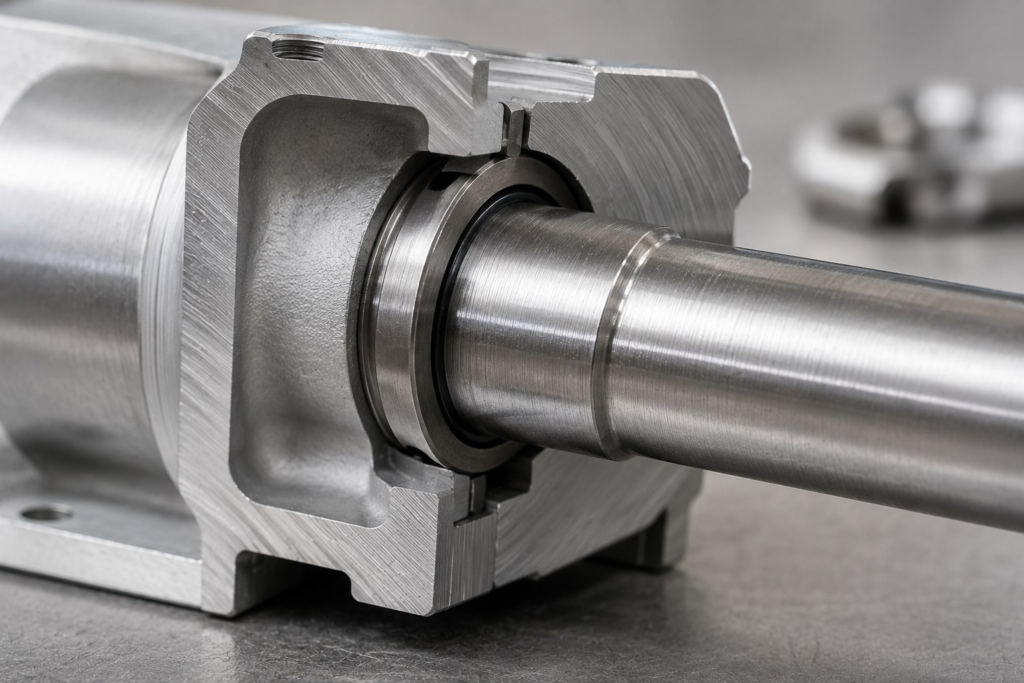
Figure: Tolerance decided during DFM determines whether the DFA assembly step is a slide-fit or a fight.
DFM in Practice: Three Manufacturing Processes
DFM rules aren’t universal — they’re specific to the process making the part. A rule that protects an injection-molded housing can be irrelevant to a CNC-machined bracket. Three of the most common processes VYRSTA reviews against:
Injection Molding
Uniform wall thickness prevents sink marks and warping as plastic cools unevenly. Draft angle — typically 1 to 2 degrees minimum on vertical walls — lets the part release from the mold without dragging or scarring. Ribs should stay at 50 to 60 percent of the wall thickness they attach to, to avoid sink marks showing through the opposite face.
CNC Machining
Internal corners need a radius that matches an available cutting tool — a true sharp internal corner can’t be machined without EDM. Deep, narrow pockets increase cycle time and tool deflection risk. Hole depth beyond roughly four to five times the diameter starts to challenge standard drilling and hurts positional accuracy.
Sheet Metal
Bend radius has a practical minimum tied to material thickness and grain direction, below which the metal cracks at the bend. Features placed too close to a bend line distort during forming. Hole diameters too close to an edge or another hole risk tearing during punching.
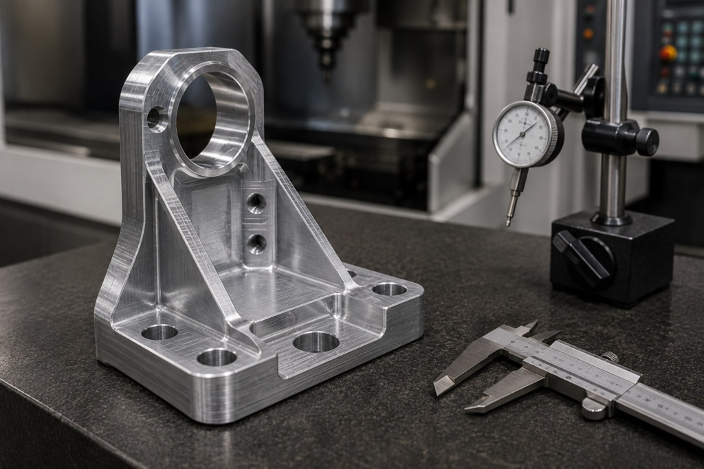
Figure: Internal fillets sized to an available cutting tool — the difference between
one operation and a second EDM step.
Tolerancing and GD&T: The Language That Actually Controls Fit
A generic title-block tolerance — a blanket ±0.1 mm applied to every dimension on a drawing — is where most DFM/DFA reviews find their next problem. It assumes parts deviate only in straight-line distance. They don’t Manufactured features tilt, bow, warp, and rotate, and a linear tolerance has no way to describe any of that. Controlling how a part is actually allowed to vary — not just how big it’s allowed to be — is what Geometric Dimensioning and Tolerancing (GD&T, per ASME Y14.5) and its international counterpart, ISO GPS (per ISO 1101), exist to do.
The principle underneath both standards is straightforward: whatever the designer specifies on the drawing has to be the same thing the quality engineer measures on the inspection report. Form controls — flatness, cylindricity, profile — are evaluated independently of any reference. Location and orientation controls — position, perpendicularity, concentricity — are measured against a defined datum reference frame. Separating “how round” from “where located” lets a team tighten only the geometry that actually matters to function, instead of tightening every dimension out of caution.
General Tolerances and Standards in Production Use
Not every feature on a drawing needs an individual callout. General tolerance standards set the default for everything that doesn’t:
| Standard | What It Governs |
| ISO 2768-1 / -2 | Default linear, angular, and geometric tolerances for un-toleranced features (classes f/m/c/v and H/K/L) |
| ISO 22081 | Modern ISO GPS replacement for ISO 2768 — a default profile tolerance referenced to a primary datum frame |
| ASME Y14.5 / ISO 1101 | Feature-level geometric control — GD&T symbols, datum reference frames, position and profile tolerances |
| ISO 286 | Limits and fits for mating cylindrical features — hole/shaft tolerance grades (e.g. H7, g6) |
| ISO 1302 / ISO 21920 | Surface texture specification — Ra, Rz, and profile parameters tied to function |
| ISO 13715 | Edge state definition for sharp or undefined edges — burr and chamfer limits |
Limits and Fits: What H7/g6 Actually Means
When a shaft has to enter a bore — a bearing seat, a dowel hole, a sliding piston — the fit between the two is specified with an ISO 286 hole/shaft pair, not a pair of independent ± tolerances. Uppercase letters describe internal features (holes), lowercase letters describe external features (shafts):
| Fit Type | Example | Result |
| Clearance | ⌀25 H7/g6 | Guaranteed 0.007– 0.041 mm gap — free sliding or rotation |
| Transition | ⌀25 H7/k6 | 0.019 mm clearance to 0.015 mm interference — precise location, light press or tap to seat |
| Interference | ⌀25 H7/p6 | 0.001–0.035 mm interference — rigid press fit, no keyway needed |
Tolerance Stack-Up: Worst-Case vs. Statistical (RSS)
Before drawings release for tooling, the individual tolerances on every part in an assembly have to be checked together, not just one at a time. Two methods are standard practice.
Worst-case analysis assumes every part hits its extreme limit simultaneously — it’s the sum of the individual tolerances, and it guarantees 100% interchangeability but usually forces every part tighter than it needs to be.
Root-Sum-Squares (RSS) analysis treats manufacturing variation as statistically distributed and takes the square root of the sum of squares — it accepts that all parts landing at their worst case simultaneously is vanishingly unlikely, and it typically holds a 99.73% assembly yield at a ±3σ process.
| TOLERANCE & COST ESCALATION ANALYSIS 5 parts, ± 0.10 mm each: — | 5 parts, ± 0.10 mm each | — | Worst-Case Stack: ± 0.50 mm | Worst-Case Stack | ± 0.50 mm | RSS Stack: ± 0.224 mm | RSS Stack | ± 0.224 mm | Tolerance Gained: 2.2× | Tolerance Gained | 2.2× |
Switching from worst-case to RSS on the same 5-part stack more than doubles the tolerance budget available to each individual part — without changing how the assembly performs.
This is also where DFM and DFA formally meet: the fit called out in a GD&T note is what a DFM review checks a single part can hold, and it’s what a DFA review depends on to guarantee the assembly goes together the same way every time.
DFA in Practice: Reducing Assembly Risk
Where DFM rules vary by process, DFA principles hold across almost any product: reduce parts, reduce fasteners, and remove the possibility of assembling something the wrong way.
- Part consolidation — combining brackets, standoffs, or guides into a single molded or machined feature wherever the tooling cost is justified by the assembly time saved.
- Fastener reduction and standardization — fewer screw sizes and types means fewer bins at the assembly station and fewer wrong-fastener errors.
- Self-locating features — chamfers, pilot pins, and alignment ribs that guide a part into position before the fastener is even started.
- Poka-yoke geometry — asymmetric mounting holes or keyed connectors that make it physically impossible to install a part backwards or upside down.
- Single-direction assembly — designing so parts stack and fasten from one direction (typically top-down), avoiding flips and re-orientation on the line.
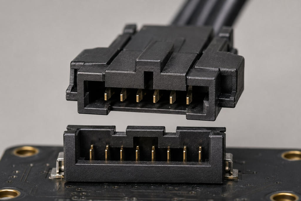
Figure: A connector that only fits one way removes an entire category of assembly-line
rework.
CMF: Where Finish Becomes an Engineering Spec, Not a Cosmetic Choice
CMF — Color, Material, and Finish — is usually treated as a styling decision made after the engineering is locked. That’s backwards. A texture, a plating thickness, or a surface roughness callout changes real dimensions, real tolerance budgets, and real tooling cost, which means CMF decisions belong inside the same DFM/DFA review as wall thickness and fastener count — not bolted on afterward.
Surface Texture Is a Draft-Angle Decision
A textured finish specified per VDI 3400 or Mold-Tech grain standards doesn’t just change how a part looks — it changes how much draft angle the mold needs to release it. Every 0.025 mm of texture depth adds roughly 1.0° of required draft on top of the baseline 1.0–1.5° minimum. Specify a deep, aggressive grain without adjusting draft, and the part drags on ejection — scuffed, stress-whitened, or stuck in the tool.
Surface Roughness by Function, Not by Habit
Surface finish is specified under ISO 1302 / ISO 21920 using Ra (average roughness) and Rz (peak-to-valley height), and the right value is set by what the surface does — not by defaulting to the smoothest option available.
| Finish Level | Typical Ra | Where It Belongs |
| Coarse machining | 3.2–6.3 µm | Non-mating clearance surfaces |
| Precision milling | 1.6–3.2 µm | General structural mounting faces |
| Reaming / grinding | 0.4–0.8 µm | Static O-ring seal seats, bearing fits |
| Lapping / honing | 0.05–0.2 µm | Dynamic, high-pressure fluid seals |
The jump matters economically, too: tightening a ground face from Ra 0.8 µm to a lapped Ra 0.1 µm can raise machining cycle time and tooling wear by 300–500%. Specifying a finer finish than the function needs is a cost decision, not a quality one.
Plating and Coating Change the Part’s Actual Dimensions
Anodizing and plating add material thickness, which has to be accounted for in the tolerance stack, not treated as a cosmetic afterthought:
Finished Dimension = Machined Dimension + 2 × (Coating Thickness)
- Anodizing Type II (sulfuric acid) — roughly 10–20 µm total growth, half into the base metal and half outward.
- Anodizing Type III (hardcoat) — a dense ~50 µm layer; skip the compensation on a precision bore or sliding shaft and the assembly binds.
- Electroless nickel plating — a highly uniform 5–25 µm layer across pockets and threads, used where electroplating’s uneven corner build-up isn’t acceptable.
Edges Are Specified, Not Left to the Line
Sharp corners are stress concentrations, burr sites, and cut hazards, and ISO 13715 gives them an explicit symbolic language instead of leaving them to whoever’s running the deburr station. A callout like −0.2 means an external edge must carry a chamfer or radius between 0.05 and 0.2 mm; +0.3 permits an internal burr or material extension up to 0.3 mm. Controlling edge state on the drawing removes the ambiguity that otherwise gets resolved by hand-filing parts on the assembly floor.
Color, material, and finish were never purely aesthetic — they were always tolerance, cost, and manufacturability decisions wearing a design vocabulary. Reviewing CMF alongside DFM and DFA is what keeps a “premium feel” claim from becoming a line-item surprise after tooling.
The Cost of Waiting Until After Tooling
The reason DFM and DFA are treated as gates rather than optional polish is cost escalation. A change to geometry is inexpensive when it’s still a 3D model. The same change costs materially more once it’s a machined prototype, more again once tooling exists, and the most once the product has already shipped and the fix has to route through service or recall.
| TOLERANCE & COST ESCALATION ANALYSIS Concept / CAD: 1× | Concept / CAD | 1× | Prototype: ~10× | Prototype | ~10× | Tooling Cut: ~100× | Tooling Cut | ~100× | Post-Launch: ~1000× | Post-Launch | ~1000× |
Illustrative escalation, consistent with the widely cited “rule of ten” in design change-cost literature — actual multipliers vary by industry, tooling complexity, and program.
When in the Timeline DFM/DFA Should Happen
DFM and DFA reviews belong in the detailed design phase — after the concept and general layout are settled, but before drawings are released for quotation or tooling. Early enough that geometry can still change cheaply; late enough that the review isn’t chasing a moving target.
Running the review earlier than that wastes effort on features that haven’t stabilized. Running it later —
after a supplier has already quoted tooling — turns every finding into a change order instead of a design decision.
Simulation findings should land before this window closes, not after. A CFD analysis that flags a thermal hotspot or a FEA structural simulation that flags a stress concentration both change part geometry — and geometry changes are what a DFM/DFA review is built to absorb cheaply, before tooling is cut.
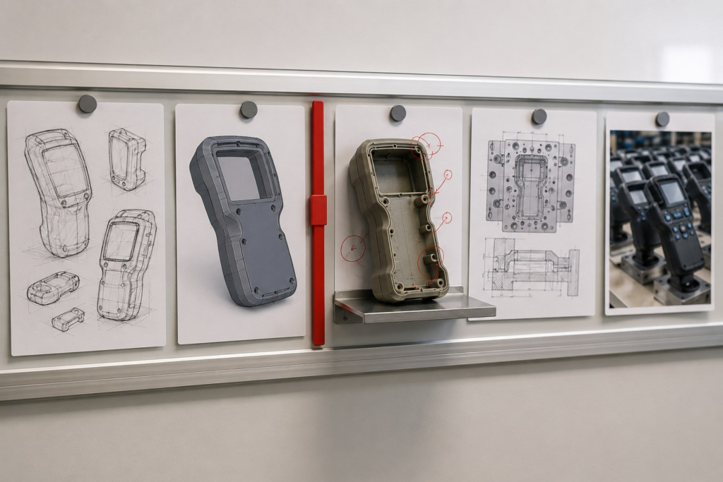
Figure: The review window: geometry stable enough to evaluate, tooling not yet committed.
What a VYRSTA DFM/DFA Review Delivers
A DFM/DFA review isn’t a verbal opinion in a meeting — it’s a structured deliverable the design team can act on directly, tied back to the specific manufacturing process and assembly sequence the product will actually use.
| REVIEW DELIVERABLE CONTENTSDELIVERABLES INCLUDED: • Part-by-part DFM findings— wall thickness, draft, rib geometry, tolerance risk, flagged against the intended manufacturing process. • Assembly-level DFA findings— part count, fastener count, insertion direction, and poka-yoke opportunities across the full build sequence. • Marked-up CAD or drawings— every finding shown directly on the geometry it affects, not described in isolation. • Risk ranking— findings sorted by cost and schedule impact, so the highest-leverage fixes get addressed first. • Recommended design changes— specific geometry or fastener changes, not just a list of problems. |

Figure: Findings land on the drawing itself, not in a separate document disconnected from the geometry.
One product line, tracked end to end — sketch, CAD, prototype, tooling, assembly, inspection, and finished part — shows what continuous DFM/DFA discipline actually looks like in practice, not a single gate but a check repeated at every stage.
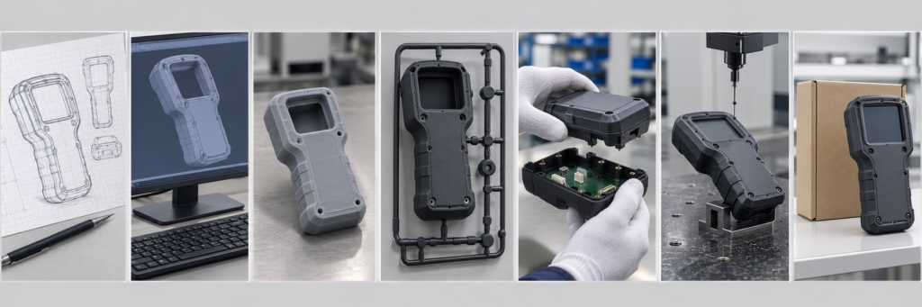
Figure: The same discipline, applied at every stage — not a single review, but a continuous check.
Frequently Asked Questions (FAQ)
Q: What is the difference between DFM and DFA?
A: DFM (Design for Manufacturing) focuses on how easily and cheaply each individual part can be made — wall thickness, draft angles, tolerances, tooling complexity. DFA (Design for Assembly) focuses on how easily the finished parts go together — part count, fastener count, insertion direction, and error-proofing. DFM asks “can we make this part well,” DFA asks “can we put this product together well.”
Q: Do you need both DFM and DFA, or just one?
A: Most products need both. A part can be trivial to manufacture and still be painful to assemble, and a product can assemble in seconds while individual parts are expensive to mold or machine. VYRSTA runs DFM and DFA reviews together because a change made for one discipline — such as part consolidation — usually affects the other.
Q: When in the design process should DFM and DFA happen?
A: Before tooling is cut, ideally during the detailed design phase once geometry is stable but before drawings are released for quotation. Changes made at this stage cost a fraction of what the same change costs after tooling exists, per the well-documented rule-of-ten cost escalation across the product development timeline.
Q: Does DFM/DFA review slow down the design schedule?
A: A structured DFM/DFA review typically adds days, not weeks, and is scheduled to run in parallel with other detailed design tasks rather than gating them. The time it adds upfront is consistently smaller than the time lost later to a failed first-article inspection, a blown tooling budget, or a redesign after launch.
Q: What is GD&T and why is it better than a blanket ±0.1mm tolerance?
A: A blanket linear tolerance assumes parts only vary in straight-line size. In reality manufactured features tilt, bow, warp, and rotate, which a linear tolerance can’t describe. GD&T (per ASME Y14.5) and ISO GPS (per ISO 1101) separate form controls like flatness and cylindricity, evaluated independently, from location and orientation controls like position and perpendicularity, evaluated against a defined datum reference frame. This lets a team tighten only the geometry that actually affects function instead of tightening every dimension out of caution.
Q: What is CMF in product engineering?
A: CMF stands for Color, Material, and Finish. It’s often treated as a cosmetic decision made after engineering is locked, but texture, plating thickness, and surface roughness all change real dimensions and tolerance budgets. A textured mold finish requires additional draft angle, anodizing and plating add material thickness that must be built into the tolerance stack, and surface roughness is specified by function, not by defaulting to the smoothest available option. VYRSTA reviews CMF alongside DFM and DFA so finish decisions don’t become cost surprises after tooling.